


“…training and deliberate practice are fundamental for improving technique and image acquisition. A successful performance, however, requires more than this. The key to clinical ultrasound lies in sound clinical reasoning and contextual image interpretation. The key is to assess the patient and then ask the right question.”
The Basics.
LIMITATIONS & BINARY THINKING
Point of Care Ultrasound is not the same as the formal ultrasound performed by a radiologist, and it won’t ever replace that modality. Furthermore, while training, image acquisition and interpretation can be very challenging for the novice, particularly in the emergency context, so keep this in mind as you learn how to scan.
POCUS has a specific setting and uses clearly defined protocols to answer clinical questions rapidly. Ideally, the approach will be simple and binary (yes/no). To illustrate, facing acute abdominal pain, a pertinent question would be: Does this patient have a gallstone? (yes/no). Instead of: what is causing this patient’s abdominal pain?
Formulating the wrong questions might be not only useless but also dangerous as it doesn’t consider the limitations of emergency ultrasound. For example, when dealing with blunt abdominal trauma, a negative FAST scan may cause a false sense of security if it’s not understood that the absence of free fluid doesn’t rule out solid organ injury.
Training and deliberate practice are fundamental for improving technique and image acquisition, particularly for the beginner. A successful performance, however, requires more than this. The key to clinical ultrasound lies in sound clinical reasoning and contextual image interpretation. The key is to assess the patient and then ask the right question.

Physics.
WHAT IS ULTRASOUND?
In basic terms, a transducer probe casts high-frequency (2-15 MHz) sound waves, which are transmitted through the body. The waves penetrate and bounce on the tissues, and later some return to the probe. The returning echoes stimulate the probe to produce electricity, which is interpreted in the form of an image on the screen.
Ultrasound waves are not transmitted well through air and require a ‘medium’ for transport. Gel is used between the probe and the patient’s skin as a ‘coupling’ agent. Be generous about it.
PIEZO-ELECTRIC EFFECT
Classically, the transducer contains a piezoelectric crystal with the property to be electrically stimulated. An electromagnetic stimulus passes through the crystal causing it to vibrate and so generating sound waves.
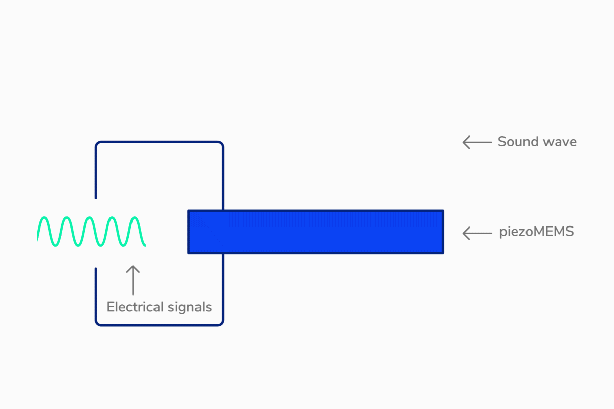
After each pulse of sound has been produced, the transducer switches to receiving mode and ‘listens’ to the soundwaves that come back.
The waves travel at different speeds through different tissues and are reflected, absorbed or scattered at the boundaries between different media (tissue, liquid, air). When sound waves hit these boundaries, echoes are sent back to the receiving probe, causing the crystal to vibrate and produce an electrical signal which is detected and analysed to form the image.
IMAGE FORMATION
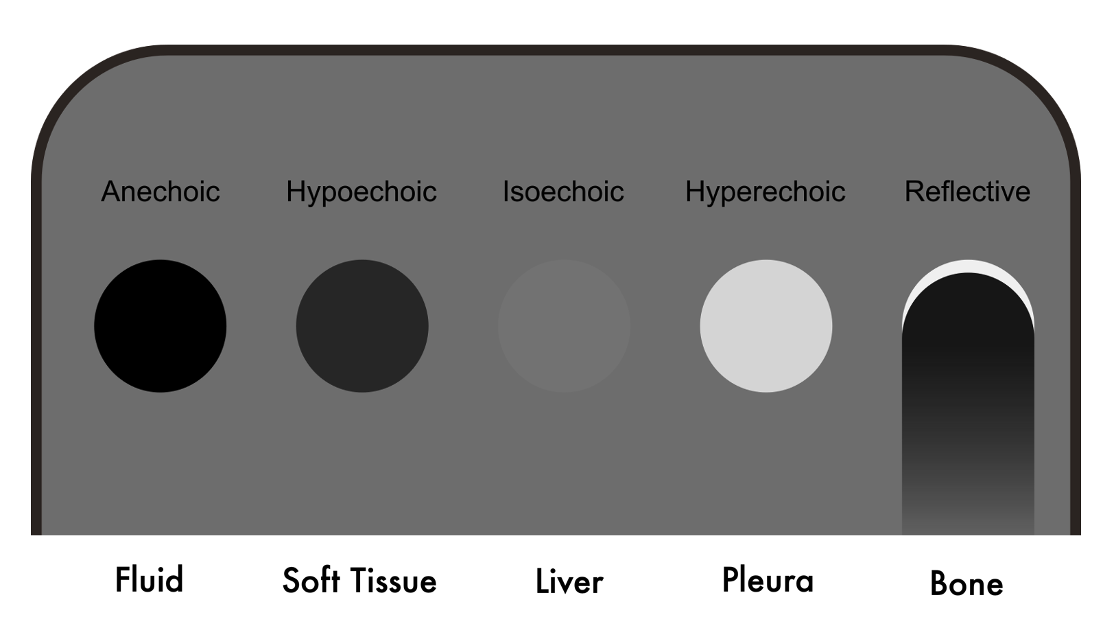
The US machine process the vibratory-electrical signal to form an image, which is made up of tiny pixels ranging from white, through shades of grey, to black. The brightness of each pixel corresponds to the amplitude of the returning echo, a white area is called echogenic, and a darker or black area is hypoechoic or anechoic (1).

The horizontal position on the image is determined by what sound waves generated the echoes detected, and the vertical position reflects the time taken for the echo to return following the initial pulse. Echoes that return in a shorter period of time appear on the screen as closer to the probe, whereas echoes from deeper tissues take longer to return and position themselves farther from the probe (1). In other words: time is distance.
RESOLUTION

ATTENUATION
ACOUSTIC IMPEDANCE & ECOGENICITY
Each tissue or ‘medium’ has a different impedance to the passage of the sound waves, this is called acoustic impedance. Basically, this property describes the capacity that each ‘medium’ has for transmitting sound waves through the mater. Namely, fluids (bladder, liver) are very good at transmitting sound, whereas air (lung, hollow viscus) cannot transmit sound waves, scattering or reflecting them instead. The greater the difference in acoustic impedance at a boundary, the greater the reflection or refraction of the sound wave. One clear example of this is the interface between the liver and the lung. The diaphragm is highly refractive because it lies in between tissues with a notoriously contrasting acoustic impedance.

In sum, the varying properties and ‘textures’ of tissues will produce different echoes. Consequently, the tissues seen in the image will have differing ‘echogenicities’.
Orientation.
To correctly interpret the layout of the image on the screen, it is fundamental to understand the disposition of the patient’s anatomy and the planes of cut. Hence, it may be helpful to consider that the image is produced by a flat beam that cuts the body in a determined plane. The skin is always at the top of the screen and deeper structures towards the bottom.
Adequate Anatomy identification will be ensured by always holding the probe in the proper orientation. To this end, the transducer probe has a marking bump or notch on one of its sides, and the screen has a marking dot on one side of the image.
More often than not, the marking dot on the screen will be at the top left of the image. Nonetheless, this conventional orientation will be reversed on a cardiac preset, which could lead to confusion. More important than convention, however, is that the user analyses and clearly understand what is observed.

Anatomical Planes: 1. Transversal 2. Sagital 3. Coronal / Frontal
Transverse Plane
Longitudinal Plane


The Machine.
MODES
B-mode (Bright) is the most commonly used. The US beam is swept through the patient’s body, producing a two-dimensional (2D) scan plane, similar to the scout image of a CT scan. The tissues are represented on the screen by countless tiny grayscale dots, which together form a 2D image.
In M-mode (Motion), a single line of B-mode echoes is continuously updated through time. The on-screen horizontal axis represents time, and the vertical axis represents depth. This mode correlates with movement along one line of the scan. The classic example is using it to assess the movement of the pleura when looking for pneumothorax, but it is perhaps more helpful in echocardiography to evaluate the mitral or tricuspid annular plane excursion during systole (MAPSE, TAPSE).
TWEAKS & KNOBS
There are multiple manufacturers and models of ultrasound machines in the market, which also vary in quality, capabilities, size, portability and price. Despite some variation in the keyboard layout and labelling of the knobs, almost all machines share standard features. The fundamental ones will be described here and should be identified in your specific device.

Gain
Used to increase or decrease the amount of returning echoes, respectively making the image whiter or darker. At the appropriate gain setting, the image should be neither too bright nor too dark and uniform from top to bottom. Fluid should appear black (anechoic).
Time Gain Compensation
Usually controlled by a set of sliders on the keyboard. It allows for adjustment of gain at different levels of depth in the image. Remember, time is distance.
Depth
Used to adjust the depth setting of the image. Depth is decreased to maximize the image detail when scanning superficial structures and is increased to visualize deeper structures. To measure depth, there is a centimetre graded scale lying vertically to the right of the screen.
Focus
Improves resolution at a particular depth in the image. It is not available on all machines, and many modern systems now have an autofocus feature that obviates the need to do it manually.
Freeze
It allows freezing the image prior to performing measurements or saving the image.
The Panic Button
Every machine will have a 2D / B-Mode knob or button, think of it as the panic button. Pressing it will override the current screen, mode or setting that you got to without knowing how and get the screen back to a ‘clean’ 2D scanning modality.
PROBES
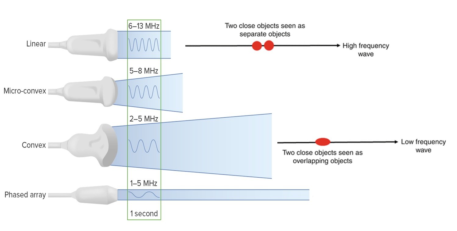
There are different kinds of transducer probes available, although the most commonly used in the emergency department are the linear array, curved array and phased array probes. The main difference lies in the shape of the ultrasound beam that they cast, and the frequency of the sound waves.

Linear array transducers cast high frequency (6-12 Mhz) soundwaves, producing a high-resolution rectangular image. Due to the high frequency, there is a limitation to the depth of the image. The higher the frequency, the higher the resolution, but the waves have less penetration to deeper structures. Therefore, linear probes are mostly used to obtain detailed images of superficial structures.
Curved transducers are essentially linear probes constructed with a curve, providing a wider field of view. Because they work with low frequencies (1-5 Mhz), the image is of less resolution. However, low frequency allows reaching into deeper structures. Hence, they are mostly used for abdominal scanning.
Phased array or sector transducers cast low frequency (1-5 Mhz) soundwaves. The probe's design allows both a broad, deep field of view and a small footprint at the probe's head. As a result, this probe is ideal for obtaining images of the heart by scanning in between the ribs, yet it can also be used to scan the abdomen or the lungs.
Linear

Curved
Phased
BUTTERFLY IQ
This particular model is perhaps a more modern approach to ultrasound. The construction of the probe has dismissed the classic piezoelectric crystal, replacing it with what is advertised by the manufacturer as the world's only Ultrasound-on-Chip™ technology. In very basic terms, the silicon chip behaves as a speaker with the ability to modulate and change its ultrasound frequency. Consequently, it allows a high versatility to the user as the linear, curved and phased array settings are integrated into one probe. Furthermore, the machine is designed as a handheld, portable ultrasound which connects to a smartphone or tablet and can easily be stored in the pocket. Certainly, these benefits are weighted against some logical drawbacks such as image quality, resolution or battery life.
Still, I use this device in my daily practice and believe it to be the future of routine physical examination. In the limited-resources setting, it became an invaluable diagnostic tool, allowing me to obtain information that otherwise would have been impossible.
Linear

Curved

Phased
Basic Movements
Basic Movements
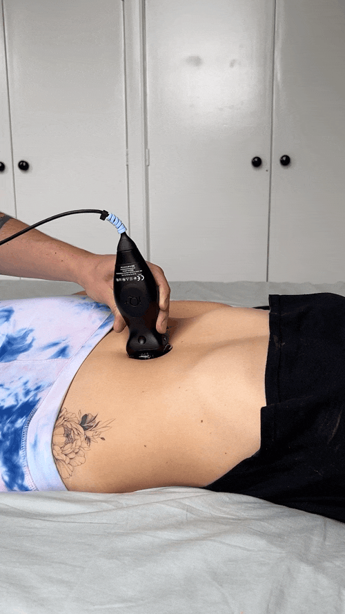
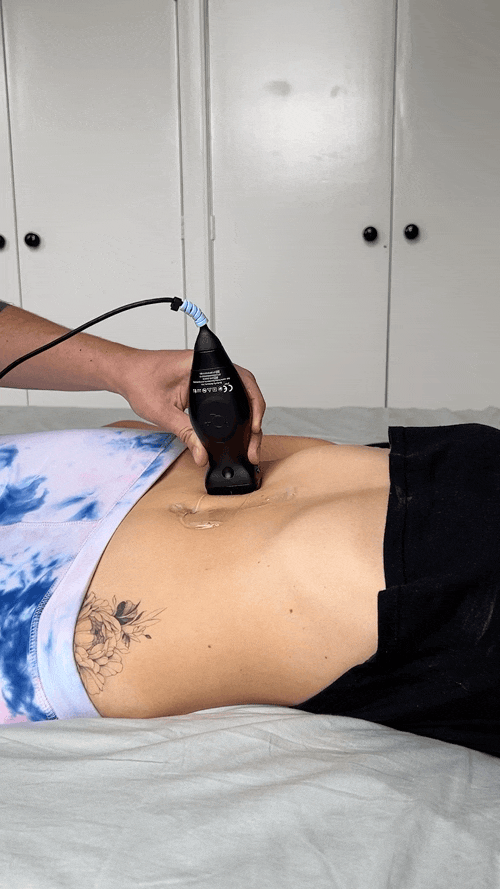
Probe Handling
-
![]()
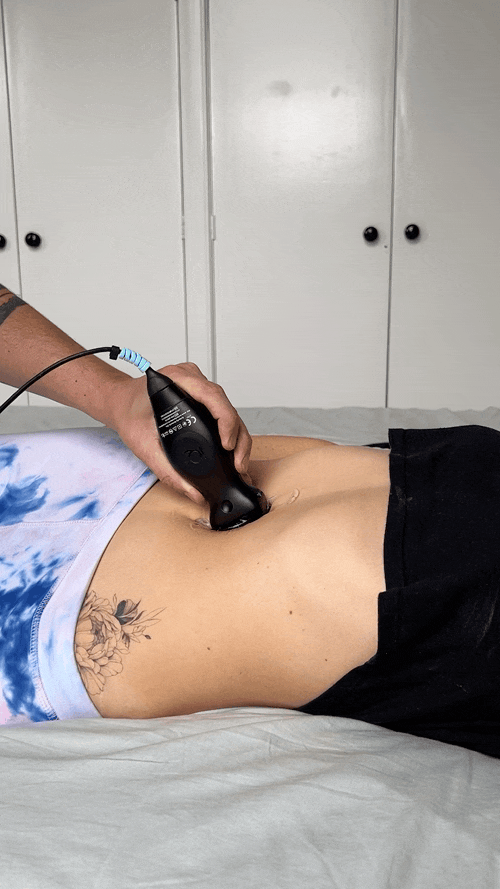
Slide.
Motion across the body following the long axis of the probe and with a consistent angle of insonation at 90º to the target.
-
![]()
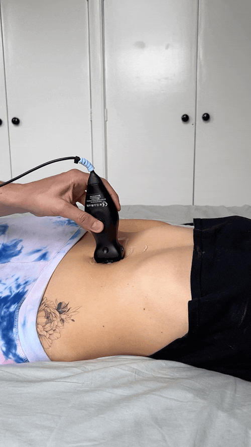
Sweep.
Motion across the body following the short axis of the probe and with a consistent angle of insonation at 90º to the target.
-
![]()
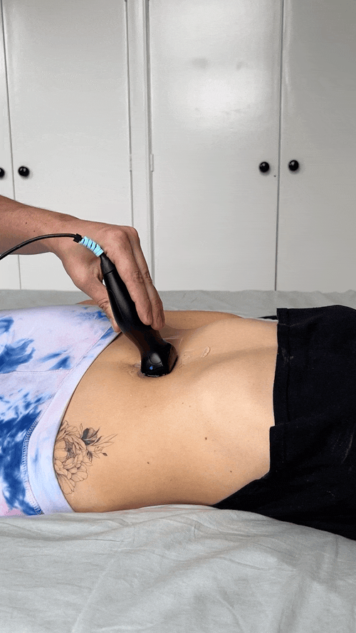
Rock.
Motion along the long axis of the probe over a fixed point on the body while changing the angle of insonation away from 90º.
-
![]()
Fan.
Motion along the short axis of the probe over a fixed point on the body while changing the angle of insonation away from 90º.
-
![]()
Rotate.
Rotational motion of the probe in a clockwise or counterclockwise direction over a fixed point on the body.
-
![]()
Compress.
Compression by applying force on the probe towards the patient’s body.

Artefacts
〰️
Artefacts 〰️
Artefacts
Artefacts

For lack of a better word, an artefact is a Mirage. It is the machine’s translation to sound waves being enhanced, reflected, bounced or scattered. It is an image that does not correlate to the patient’s anatomy at that location.
Artefacts can be useful in the interpretation of an image or can obscure information. In most cases, however, artefacts just represent normal findings.
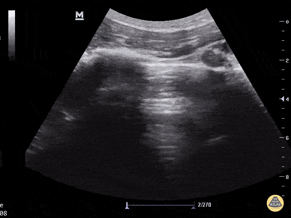
REVERBERATION
It occurs when the sound waves bounce between a reflective structure and the probe, or in between two highly reflective parallel structures; it can also occur because of a lack of gel. The bounce results in several echoes that translate to the screen as multiple, evenly spaced, parallel lines. The classic example is the ‘A lines’ in the lung, which are caused by sound reflection between the pleura and the transducer, representing a normal finding.


MIRROR IMAGE
This is caused by sound-wave reflection generated by large, highly reflective, curved interfaces such as the diaphragm or pericardium. The reflected sound wave deviates and the return time of the echo is delayed. Thus, the resulting on-screen image is placed deeper than its actual location (time is distance). Additionally, for the artefact to be present, the structure beyond the reflective interface requires to be a poor sound conductor (normal lung) or otherwise would avoid sound reflection.


A ‘mirror image’ of the reflected structure appears on the other side of the reflective interface; for example, in normal conditions, a mirror image of the liver can be seen on the cranial side of the diaphragm. In the presence of pleural effusion, the mirror image is not to be seen due to the liquid in the chest cavity, which acts as a good conductor of sound.
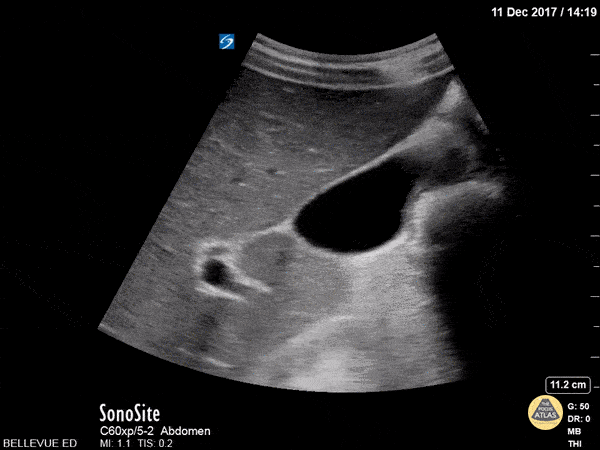
ACOUSTIC ENHANCEMENT
This artefact is seen when sound waves pass through a fluid-filled structure (gallbladder, urinary bladder, cysts, blood vessels). In these cases, the fluid allows more sound energy to pass through (less attenuation) and acts as an ‘acoustic window’ to deeper structures. Accordingly, tissues beyond the fluid are visible and appear brighter. In pelvic scans, for example, a full bladder acts as an acoustic window to help visualize deeper tissues like the uterus.


ACOUSTIC SHADOWING
This is the opposite of acoustic enhancement. If sound waves hit a highly reflective structure like bone cortex or calculi, the sound energy is reflected or scattered. The remaining energy struggle to reach deeper structures (attenuation) and the tissues behind the reflective structure appear dark. In case no sound wave penetrates the structure, acoustic shadows are produced (black).


This can be useful when scanning the gall bladder, as gallstones can be recognized by their posterior shadow. Shadowing, however, can be problematic. For example, shadowing caused by ribs in the upper abdomen or chest can difficult the visualization of deeper structures, and veins can be obscured by calcified arteries in older patient’s legs.
EDGE SHADOWS
These are shadows caused by the curved walls of some round structures, for example, the gallbladder or blood vessels. They occur owing to the strong refraction of the sound wave over a convex surface.


Author: Felipe Urriola P. | Published: 23 August 2022
Reference.
Bowra, Justin; McLaughlin, Russell; Atkinson, Paul; Henry, Jaimie. Emergency Ultrasound Made Easy, Third Edition. 2022. Elsevier Health Sciences.
Basaure, Carlos; Clausdorff, Hans; Riquelme; Felipe. Ultrasonido Clínico, First edition. 2018. Emergency Medicine Residency Program, Universidad Católica de Chile.
The Pocus Atlas. https://www.thepocusatlas.com
Taming the SRU. http://www.tamingthesru.com/knobology
Nephropocus. https://nephropocus.com/2019/06/19/mirror-image-artefact/
Boston University Emergency Medicine. https://www.bumc.bu.edu/emergencymedicine/program-welcome/ultrasound/
Sunnybrook Research Institute. https://sunnybrook.ca/research/content/?page=sri-magazine-2017-all-hocus-no-pocus